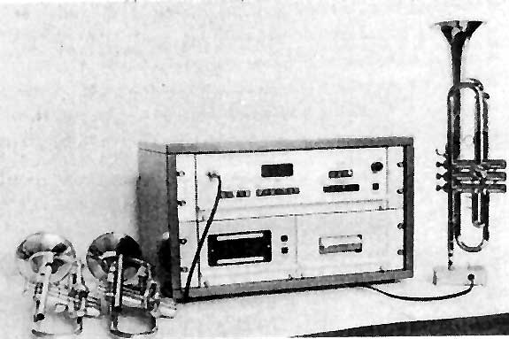
Fig. 1 The apparatus designed to locate automatically and track the resonances of a wind instrument.
Digital displays indicate the intonation and amplitude of the resonances.
Systematic approach to the correction of intonation in wind instruments
Richard A. Smith
Boosey and Hawkes Ltd, Edgware, Middlesex, UK and Department of Physics, Southampton
University
Geoffrey J. Daniell
Department of Physics, Southampton University, Southampton SO9 5NH, UK
The effect of perturbations in the bore diameter on the intonation of wind instruments is investigated. From measurements of the bore and the amplitude of the standing waves, a modified bore shape is calculated to give any desired correction in intonation. |
Musical instruments have evolved over the centuries very much
by trial and error. In spite of scientific investigation, many undetermined
factors critically affect the performance of instruments, and empirical methods
of design are still necessary. Some features, however, are easily amenable
to quantitative treatment, and we present here the results of some calculations
and experiments on improving the intonation and tone colour of the trumpet.
All brass instruments have acoustical and mechanical inadequacies for which
most players automatically compensate1. To the
average listener an instrument may sound perfectly in tune but this largely
results from the competence of the player who may be able to 'lip' a note by ± 1
semitone, usually at the expense of tone colour. Similarly, the intonation
of inexperienced players tends to be more affected by the deficiencies of their
instruments.
The frequency of a note produced by a trumpet is determined by a complex interaction
between the vibrating air column in the instrument and the player's lips. It
is also affected by acoustical feedback to the player's ears, and differences
of more than 10 cents (1 cent = 0.01 tempered semitone) occur when different
players use the same instrument. The frequency is, however, always very close
to a resonance frequency of the air column in the trumpet.
The necessity of first eliminating the contribution of the individual player
to the intonation has been recognized by several workers2-7, but no satisfactory
method of artificial excitation has yet been described. We have used a modification
of the method originally described by Webster3 to measure the resonance frequencies
of the air column in the trumpet. The apparatus (Fig. 1) operates over the
frequency range C2 (65 Hz) to B7 (3,951 Hz) (C4 = middle C) and includes an
automatic locking device for the location and tracking of resonance peaks.
It gives a digital display and printed record of the amplitude and intonation
of each resonance (in cents) relative to the equitempered scale.
It was found that the frequency of each resonance of an instrument corresponded
closely with the mean of the frequencies produced for this note by a number
of players, so that observations with this apparatus can therefore be used
for the basis of quantitative measurement of the intonation of the instrument.
Resonances and tone colour
The resonance frequencies are principally determined by the shape of the bore
of the trumpet, and evolution has produced a bore shape with resonances fairly
close to the appropriate notes of the equitempered scale. Unfortunately intonation
is not the only consideration in fixing the resonances as the following example
shows.
Figure 2 shows the first 10 resonances of the tube with their corresponding
equitempered frequencies.
 |
|||||||||||
| Resonance | 1* |
2 |
3 |
4 |
5 |
6 |
7* |
8 |
9 |
10 |
|
| Note | Bb2 |
Bb3 |
F4 |
Bb4 |
D5 |
F5 |
Ab5 |
Bb5 |
C6 |
D6 |
|
| Frequency (Hz) | 116.54 |
233.08 |
349.23 |
466.16 |
587.33 |
698.46 |
830.61 |
932.33 |
1046.5 |
1174.7 |
|
where
In deriving this, it is necessary to take dS zero at both ends of the instrument so that the boundary conditions are not changed. The values of Pn(x) used above are taken to be normalised so that
This implies that the dimensions of P are L-3/2, and not those of pressure. An alternative expression for Gn(x) can be derived using equation (1)
We wish to prescribe dfn and
calculate dS(x). It is
clear that the solution is not unique and we shall seek the 'smoothest' change
in the bore that produces the required frequency shifts. It may be inconvenient
to make changes over the whole instrument, because of the valves and tuning
slides, and we shall restrict them to the section x = 0 to x
= l.
To avoid discontinuities in the bore we need dS(0)
= 0 and dS(l) = 0.
A suitable measure of smoothness is the mean square derivative

and we minimise this, subject to the constraints that s(x) produces the required frequency shifts using Lagrange's method of undetermined multipliers, that is we minimise
The Euler equation for this problem is
Integrating twice gives
A and B are arbitrary constants of integration and they
can be chosen to make dS(0)
= 0 and dS(l) =
0,
and mm is
a multiple of lm.
Substituting this into (2) gives N linear equations which,
together with the conditions on dS,
determine the N+2 constants mm , A,
B. Equation
(6) then gives the required change in bore.
The reader may wonder why we have used the 'smoothest' perturbation
rather than the 'smallest' one. If we define
and find the function s(x) that minimises this and produces the required frequency shifts we get
![]()
This cannot, however, be used as a solution to our problem as it does not
ensure that dS(0) = 0 and dS(l)
= 0.
The eigenfunctions for the standing waves
To perform the calculations of the previous section the functions Pn(x) are
required. Although it is possible, in principle, to calculate these given
the cross-sectional area of the trumpet, it is undoubtedly easier to observe
them.
In a standing wave, when damping is very small, the oscillations have the
same phase at all points between adjacent nodes, and the phase changes by p across
each node. The result is not exact if damping is included, but as we have neglected
damping, even in equation (1), there is no advantage in observing the phase
of the pressure oscillations, and we assume the phase is 0 or p.
The function Pn(x) is therefore given
by the observed pressure amplitude between alternate pairs of nodes and minus
the observed pressure in the gaps.
The derivative dPn/dx is also required. Because of the well known dangers of
numerical differentiation we obtain this by integrating equation (1) giving
The value of the constant of integration C is found by integrating again, thus introducing another constant, and finding both constants by satisfying the equations at two particular values of x.
Varying the length of pipe over which the perturbation is made
An interesting result can be derived about the mean square perturbation, which
can be evaluated using equation (7). This can be differentiated with respect
to l, bearing in mind that the numbers m depend
on l. The derivatives
of m can be eliminated by differentiating
equation (2) and we get the remarkable result
It follows that ![]() is
never positive, and the mean square value of the perturbation required always
decreases as we spread the perturbation over longer lengths of the tube.
is
never positive, and the mean square value of the perturbation required always
decreases as we spread the perturbation over longer lengths of the tube.
Asymptotic results
The high eigenvalues of a Sturm-Liouville equation have simple asymptotic distributions9.
When n is large, fn ~ nc/2L and
in which qn depends on the boundary conditions. A musical instrument like the trumpet has evolved into a shape such that the frequencies of the resonances are almost uniformly spaced. In other words, the formula fn ~ nc/2L, which can be proved for large n, is in fact almost exact for all n. This suggests that the associated asymptotic eigenfunctions, Pn(x), might be good approximations for all n. This would avoid the difficult measurement of Pn(x). If the boundary conditions in the trumpet are approximately
we can show that
The integrals involved in the calculations can now be evaluated analytically.
We have tested the usefulness of this by prescribing some values for dfn,
calculating the bore shape required using the asymptotic expression for Gn(x) and
then calculating the exact frequency shifts (equation 2) that this bore
shape would produce, using the correct observed value of Gn(x).
The changes produced are found to be in the right direction, but the
magnitude of error is large. The asymptotic results can, however, be
usefully employed if (a) a rapid approximate answer is required: the
measurement of Pn(x) is
time consuming, or (b) if a very high harmonic needs adjustment, where
the observations of the resonance are impossible.
Verification of the theory
The trumpet was driven by the automatic tuner described in the first section
and the sound pressure was measured in two ways; using probe tubes inserted
radially through holes in the bore at each centimetre of the instrument's
length and using a long flexible probe drawn through the instrument. There
was little variation between the results of either method and they are shown
with the computed functions Gn(x) in Fig. 3.
Fig. 3 The physical shape of a trumpet (not to scale) with
Pn(x) and Gn(x) for
selected modes.
Fig. 4 The bore shape of a trumpet (conical
and cylindrical portions)
before and after perturbation:. ____,
perturbed bore; ----, original bore.
An earlier section has indicated the difficulties involved in deciding upon the optimum intonation of an instrument. To verify our ideas, however, these arbitrary changes were chosen: for the fifth and tenth order resonance, a change of +5 cents, for the sixth order resonance a change of -5 cents, and all other resonances to be unaltered. Similarly, the perturbed length was arbitrarily restricted to the first 0.9 m of the instrument.
Fig. 5 Relative intonation of seven resonance modes.
• , Required change in intonation; o, change obtained by perturbation.
This bore provides the 'open' notes of the instrument and additional tubing is inserted by valves to produce a chromatic scale. Consequently the effect of our perturbation is likely to be less accurate as more tubing is added; the perturbation method could be applied to this valve tubing for further correction to notes using valve tubes. Equation (8) implies that because of the relatively short length of the valve tubing, only small intonation corrections could be made in this way without unacceptably large diameter changes.
Fig. 6 The spectra of note D5 (587.33
Hz) blown by a professional musician,
(a) before, and (b) after perturbation.
Both notes were played mezzo forte in an anechoic chamber
with the microphone at 1 m along the axis of the instrument.
A graph of the new bore shape (Fig. 4) indicates a maximum change in diameter
of < 0.2 mm. This may be compared with a maximum of 0.14 mm for the smallest
mean square perturbation mentioned earlier.
The new shape was reproduced with glass reinforced plastic and its resonances
measured using the automatic tuner. There is close correspondence between the
required and measured intonation (Fig. 5); the small errors mainly arise from
the difficulty in producing a new bore to an accuracy of better than 0.02 mm.
It can be appreciated from the qualitative effects of diameter changes at nodes
and antinodes that some prescribed frequency shifts may require conflicting
diameter changes. The result in these cases is that very large increases and
decreases in diameter are required over short distances. These would be unacceptable
for a musical instrument and would also render our first-order perturbation
theory invalid. Our optimisation procedure makes sure that large changes in
diameter are not used unnecessarily.
For comparison another calculation has been made which assumes a non-optimum
bore shape given by a superposition of sine waves. The maximum diameter change
required here was 3 mm.
Curing a faulty trumpet
Although the foregoing theory is not ideally suited to the complete acoustical
design of a new instrument, the best application of this work is with the
improvement of the individual notes of prototype or production instruments.
One such instrument was found to have a weak second harmonic when playing
D5 (587.33 Hz) (Fig. 6a). As already mentioned, this harmonic uses the tenth
resonance for reinforcement; and this was found to be flat with respect to
the fifth. The tenth resonance is not normally played as a fundamental and
hence can be altered to improve the tone colour. Using our new technique
we were able to raise this tenth resonance by ten cents to give the improved
response (Fig. 6b).
This work was supported in part by the SRC and Boosey & Hawkes Ltd. We
thank Dr D. M. A. Mercer for encouragement and also acknowledge the assistance
of Mr W. Tompkins and the trumpet player, Michael Laird.
Received May 13; accepted July 21, 1976 and published in Nature, Vol. 262, August 26, 1976, pp. 761-765.
1 Smith, R. A., thesis, Univ. Southampton (1974) .
2 Martin, D. W., thesis, Univ. Illinois (1941).
3 Webster, J. C, J. acoust. Soc. Am., 19, 902-906 (1947).
4 Igarashi, J., and Koyasu, M., J. acoust. Soc. Am., 25, 122-128 (1953).
5
Hunt, F. V., J. acoust. Soc. Am., 10, 216-227 (1939).
6 Backus, J., and Hundley, T. C, J. acoust. Soc. Am., 49, 509-519 (1970).
7 Benade, A. H., and Jansson, E. V., Technical Report (Speech Transmission
Laboratory, Royal Institute of Technology, Stockholm, 1973).
8 Morse, P. M., Vibration and Sound, 2nd ed., 269 (McGraw-Hill, New York, 1948).
9 Morse, P. M., and Feshbach, H., Methods of Theoretical Physics, par. 6.3
(McGraw-Hill, New York, 1953)